
Evil Genius Labs
Purveyor of finely hand-crafted pixels. ꩜
Purveyor of finely hand-crafted pixels. ꩜
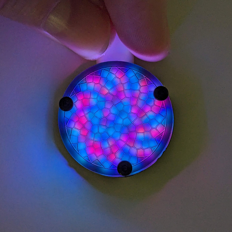
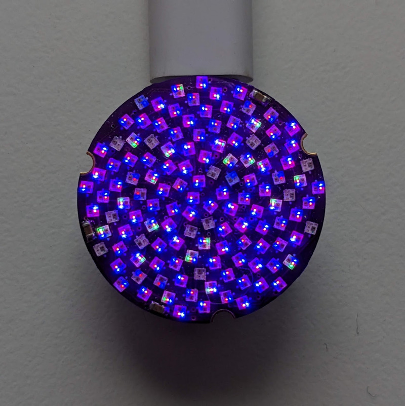
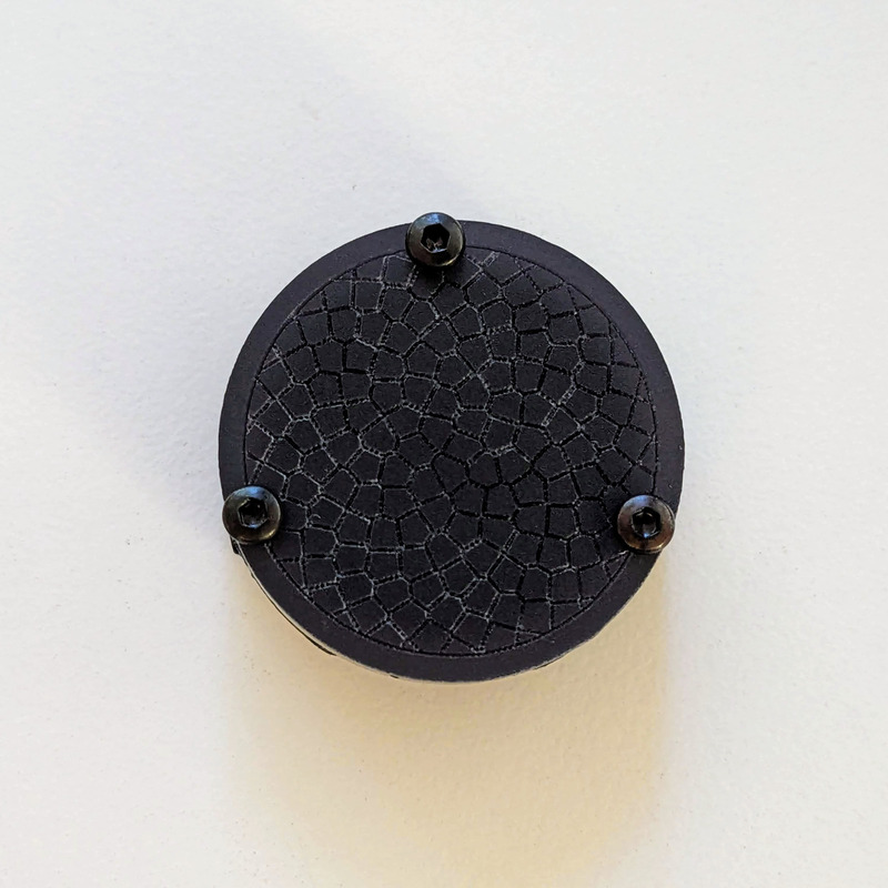

One Inch Fibonacci 128 is a tiny, beautiful 25.4mm circular disc with 128 RGB LEDs surface mounted in a Fibonacci distribution. Swirling and pulsing like a miniature galaxy, it’s mesmerizing to watch.
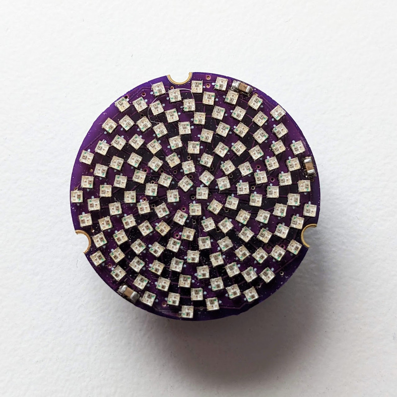
It consists of 128 XL-1010RGBC-WS2812B 1mm² RGB LEDs, arranged into a circular Fermat’s spiral pattern.
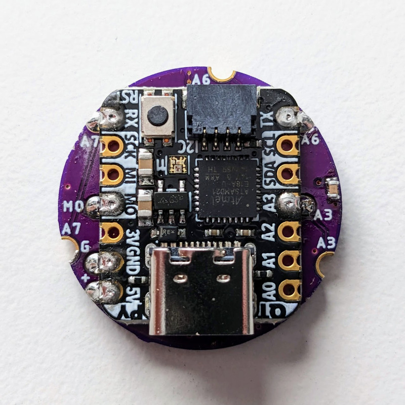
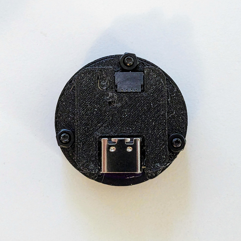
It has solder pads on the back that match the pinout of the QT Py by Adafruit, or XIAO by Seeed. It can be used by any microcontroller via the 5V, GND, and Data In pins. It also has a Data Out pad, for connecting more LEDs on the same data pin.
The three mounting holes are surrounded by capacitive touch compatible pads. They’re connected to the A0-A2 pads/pins on the QT Py footprint. The SAMD21 QT Py supports capacitive touch on these pins.
In disc phyllotaxis, as in the sunflower and daisy, the mesh of spirals occurs in Fibonacci numbers because divergence (angle of succession in a single spiral arrangement) approaches the golden ratio. The shape of the spirals depends on the growth of the elements generated sequentially. In mature-disc phyllotaxis, when all the elements are the same size, the shape of the spirals is that of Fermat spirals—ideally. That is because Fermat's spiral traverses equal annuli in equal turns. The full model proposed by H Vogel in 1979[2] is


where θ is the angle, r is the radius or distance from the center, and n is the index number of the floret and c is a constant scaling factor. The angle 137.508° is the golden angle which is approximated by ratios of Fibonacci numbers.[3]
Fermat's spiral. (2015, October 24). In Wikipedia, The Free Encyclopedia. Retrieved 02:45, February 24, 2016, from https://en.wikipedia.org/w/index.php?title=Fermat%27s_spiral
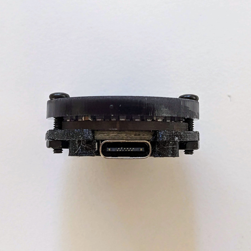
If you bought the full-assembled version, just plug your new Fibonacci into a power source using a USB-C cable and it will light up.
Touch any of the mounting screws and a wave of light should emanate from that point. Touch multiple and where they overlap the colors will combine, saturating towards white.
Press the button on the back (until it clicks) and it’ll switch to the next pattern. If you disconnect and then reconnect the power, it will also change to the next pattern.
Note: Double-check the position, alignment, and orientation of each component very carefully before soldering!
If you’re new to soldering, I highly recommend reading through a good soldering tutorial, such as the ones by Adafruit and SparkFun.
3D print files: https://www.printables.com/model/831490-1-fibonacci128-screw-diffuser-cover
Use M2x4mm screws, inserted from the back, threaded through the back cover, through the LED PCB, and into the front. This option will only let you use the touch points from the back.
This option requires acrylic with smaller 2.8mm screw holes so the screws thread into the acrylic.
You can use M2x7mm or M2x8mm screws, depending on how far out you want the ends of the screws to protrude from the front. Longer screws let you activate the touch points from the front or rear. Shorter ones will only let you use the touch points from the rear.
Open source touch demo: https://github.com/jasoncoon/fibonacci128-touch-demo/tree/f128-one-inch
[[137,125],[181,118],[201,105],[213,89],[219,71],[221,51],[218,31],[193,20],[198,39],[199,58],[195,77],[184,96],[160,114],[164,95],[176,73],[178,52],[175,33],[167,15],[154,0],[127,4],[142,18],[152,34],[158,53],[157,75],[142,108],[140,88],[140,60],[132,40],[119,26],[103,15],[85,8],[45,28],[65,27],[84,30],[101,39],[116,53],[126,74],[121,97],[106,69],[89,56],[70,49],[51,48],[32,52],[9,89],[25,78],[43,71],[63,70],[83,74],[104,89],[118,116],[84,94],[62,90],[42,94],[25,103],[11,116],[0,133],[11,159],[19,141],[32,126],[47,115],[68,109],[96,112],[81,123],[58,132],[43,145],[33,162],[27,181],[26,200],[49,216],[47,196],[50,177],[58,159],[74,143],[105,129],[94,146],[77,166],[70,186],[69,206],[74,225],[83,242],[125,255],[110,242],[99,227],[91,209],[90,188],[96,165],[114,153],[108,183],[112,205],[121,222],[135,236],[152,246],[193,234],[174,231],[156,224],[141,212],[129,195],[123,170],[130,143],[141,180],[155,198],[172,208],[191,213],[210,213],[239,181],[221,189],[202,192],[182,189],[164,180],[145,159],[164,160],[186,169],[206,170],[225,164],[241,154],[255,140],[248,113],[237,129],[222,141],[204,149],[182,150],[151,140],[170,134],[196,131],[214,121],[227,107],[236,89],[241,70]]