
Evil Genius Labs
Purveyor of finely hand-crafted pixels. ꩜
Purveyor of finely hand-crafted pixels. ꩜
I’m preparing to exhibit at Maker Faire Kansas City 2017, and trying to come up with an interactive and educational project for people to play with.
With what I have on hand, I quickly threw together a couple of breadboards, each with a Teensy, some RGB LEDs, and three potentiometers (using Paul Stoffregen’s excellent Sturdy Potentiometer Adapter for Breadboards).
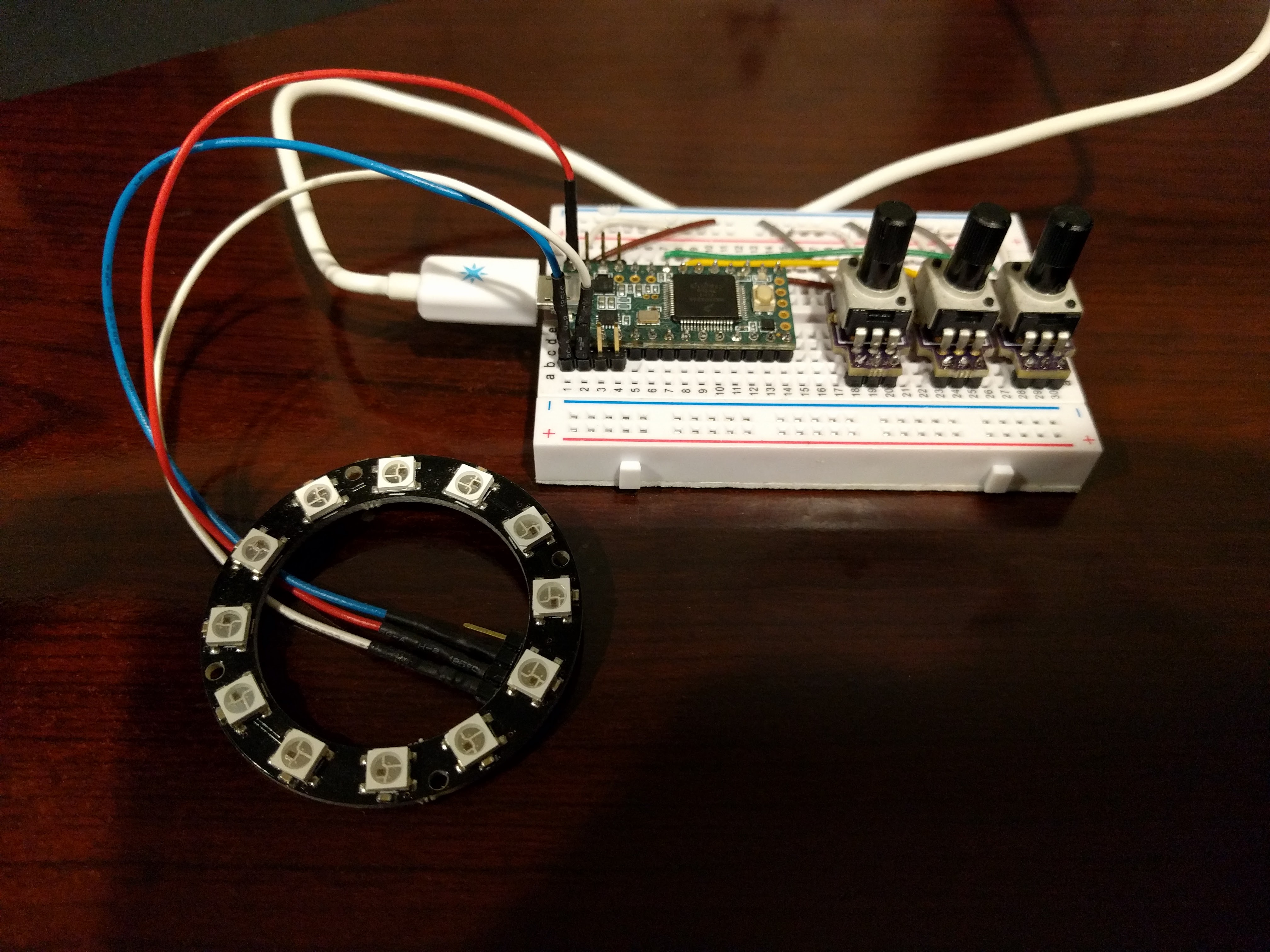
While this would work, it’s not very durable. I need something that lots of people can tinker and play with all weekend, without worrying about replacing disconnected wires.
So, I set out to design a PCB that I can assemble ahead of time, and will hopefully be durable enough to last all weekend. It will also have the bonus of being a tutorial project I can use in classes, workshops, and share online.
With these goals in mind, I created this PCB.
![]()
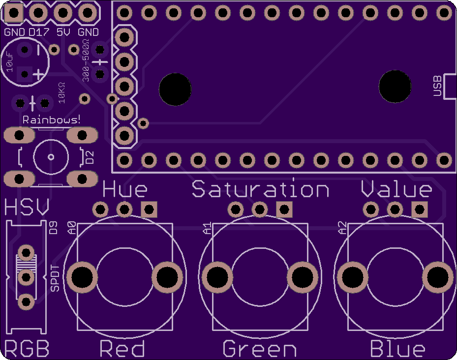
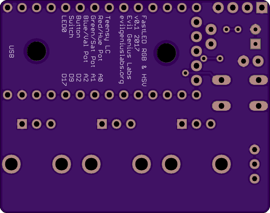
Here are the Eagle files (schematic & board)
The switch will change the potentiometers from controlling RGB to HSV. The PCB includes the NeoPixel “best practices” capacitor and resistor, and pins to connect more LEDs (a strip, ring, etc). The tactile momentary push button could be used to change modes, from the tutorial to patterns, animations, etc.
The mounting holes below the Teensy LC will allow the PCBs to be mounted on a board, so they don’t fall off the table or “walk away”.
| Name | Qty | Price | Total | Supplier |
|---|---|---|---|---|
| PCB | 1 | $4.52 | $4.52 | OSH Park |
| Teensy LC | 1 | $11.65 | $11.65 | PJRC |
| 14 Pin Header | 2 | $0.28 | $0.56 | PJRC |
| 14 Pin Socket | 2 | $0.70 | $1.40 | PJRC |
| NeoPixel Stick 8x | 1 | $5.95 | $5.95 | Adafruit |
| SPDT Slide Switch | 1 | $0.95 | $0.95 | Adafruit |
| Tactile Button (6mm) | 1 | $0.25 | $0.25 | Adafruit |
| 10k Linear Pot | 3 | $0.83 | $2.49 | Digi-Key |
| 10µF Capacitor | 1 | $0.17 | $0.17 | Digi-Key |
| 330 Ohm Resistor | 1 | $0.10 | $0.10 | Digi-Key |
| 10K Ohm Resistor | 1 | $0.10 | $0.10 | Digi-Key |
| 5 Pin Header | 1 | $0.30 | $0.30 | Digi-Key |
| 5 Pin Socket | 1 | $0.62 | $0.62 | Digi-Key |
| 4 Pin Right Angle Header | 1 | $0.45 | $0.45 | Digi-Key |
| 4 Pin Socket | 1 | $0.60 | $0.60 | Digi-Key |
| Total | 19 | $29.06 |
LEDS
I decided to go with NeoPixel Stick 8x. They are a bit cheaper and include more LEDs than the Breadboard-friendly NeoPixels.
Microprocessor
In an effort to minimize the parts cost, while maintaining the ease of assembly and use, I initially thought about using a 5V Trinket. They’re inexpensive, but still high quality, and won’t require a level shifter. They just don’t have enough inputs, so I switched to the 5V Pro Trinket. Then I remembered the Teensy LC, which is less than $2 more, has a 5V digital output pin, faster processor, more RAM, FLASH, etc. It can also be ordered from OSH Park with the PCB. I was also warned by several people that the upload process for the Trinket can be a bit tedious.
Note: Double-check the position, alignment, and orientation of each component very carefully before soldering!
If you’re new to soldering, I highly recommend buying the Teensy LC with header pins already soldered. It’ll save you some time and effort.
I also recommend reading through a good soldering tutorial, such as the ones by Adafruit and SparkFun.
Teensy LC
Carefully solder 0.1 inch (2.54 mm) header pins to the Teensy LC. It’s easiest to insert the header pins into a breadboard and soldering the Teensy on from there, as shown in this tutorial by SparkFun.
You can also use the PCB to line up and solder the pins, after you’ve added the female headers, if you don’t have a breadboard available.
You will need to solder the 5 header pins on the end of the Teensy as well. At the very least, you must solder one header pin to the hole for pin 17 on the end. This is the 5V logic output pin used to drive the NeoPixels.
PCB

I prefer to add components to the PCB from the shortest to the tallest. I find this way is easiest to hold the PCB steady when soldering. If you have a third hand, it can help as well.
Tactile Push Button
If you’re using a tactile push button that is shorter than the resistors, insert and solder it first.
Resistors
Bend one leg of each resistor 180 degrees and insert them in their respective places on the PCB. Make sure you put them in the correct places, as labeled on the PCB. Solder them in place.
Switch
If your switch has little metal tabs on the end (like the ones from Adafruit), you may need to clip them off or bend them to get the switch to sit flush on the PCB. Solder the switch to the PCB, as labeled. The orientation of the switch will not matter.
Female Headers
If you have a breadboard and some Extra-long male header pins, you can use these to align and hold the female headers while you solder.
You can also insert the Teensy LC into the female headers, then insert the female headers into the PCB to ensure they’re correctly aligned.
Insert, align, and solder the female header sockets. Make sure these are aligned correctly before soldering!
Tactile Push Button
If you’re using a tactile push button that is taller than the resistors, insert and solder it now.
Capacitor
Insert and solder the capacitor. Note: Make sure the negative lead, marked with a minus (-) sign, is inserted into the labeled negative hole in the PCB!
Potentiometers
Insert and solder the potentiometers.
NeoPixels
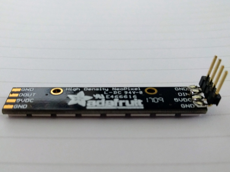
Use a third hand, clothes pin, paper clip, etc to hold the short side of the right-angle header pins on the “DIN” side of the NeoPixel strip while you solder. The longer legs of the pins, with the black plastic insulator, should be sticking up at a right angle from the NeoPixel stick.
Insert the Teensy LC into the sockets on the PCB. Make sure it’s oriented correctly, with the USB port on the edge of the PCB.
Insert the NeoPixel strip into the sockets. Double-check the alignment, comparing the labels on the strip to those on the PCB.
Knobs for the potentiometers are nice, but not required. I bought some cheap knobs on Amazon, but had to trim them down with some wire cutters, and drill out the center hole a bit to make them fit.
You could, alternatively, put a little red, green, and blue paint or nail polish on the top of the potentiometer posts.
If you have a multimeter that can measure resistance, it’s a good idea to make sure there are no shorts between power and ground on the board after assembly. You should measure infinite (or at least very high) resistance between the 5V and GND pins on the Teensy LC, NeoPixel strip, connector, etc.
After double-checking that all components are correctly aligned, you can connect the Teensy LC to a computer via a Micro USB cable.
Arduino IDE
Download and install or extract the (Arduino IDE](https://www.arduino.cc/en/Main/Software).
Teensyduino
To compile a sketch for the Teensy, you’ll need an add-on for the Arduino IDE called Teensyduino. Download and install it.
You will be asked to install additional libraries during the Teensyduino installation. Do not install all the libraries! Click ‘None’.
FastLED Library
If you’re unfamiliar with them, Adafruit’s Arduino Libraries tutorial will tell you everything you ever wanted to know about libraries, including more detailed installation instructions.
Download the latest version of the FastLED library, then unzip the file and rename the folder to “FastLED” (no quotes). Copy the file into your Arduino/Libraries folder.
Or use git to clone the FastLED repository:
cd ~/Documents/Arduino/libraries
git clone https://github.com/FastLED/FastLED.git
Either way, you’ll likely need to restart Arduino for the library to get loaded and show up.
I created a simple Arduino sketch to show how RGB & HSV work to combine to create different colors. I also included a rainbow pattern that is displayed when the momentary tactile button is held pressed.
Copy and paste the code into a new Arduino sketch:
Configure Arduino
More details coming soon…