
Evil Genius Labs
Purveyor of finely hand-crafted pixels. ꩜
Purveyor of finely hand-crafted pixels. ꩜
For free shipping worldwide, you can order directly from OSH Park: https://oshpark.com/shared_projects/Pb1joWH6
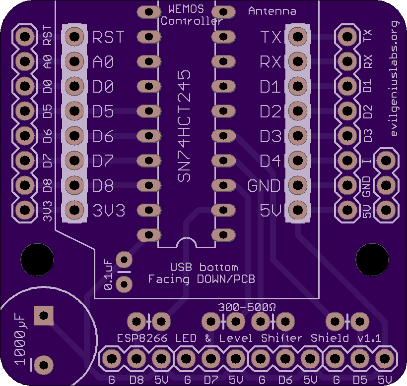
This is a shield/breakout for the Wemos D1 Mini (and D1 Mini Pro) ESP8266 board that makes it easy to control addressable RGB LEDs, such as WS2811, WS2812 (Adafruit NeoPixels), and APA102 (Adafruit DotStars). The Wemos D1 Mini is an excellent mini Wi-Fi development board, based on the ESP8266. I’ve used it extensively in development of addressable RGB LED art projects, such as my 6.5ft Rainbow Tree, Bloom v2, and Ducenti.
I made this shield because I was hand-wiring this same layout on perma-proto boards, which was time-consuming and unprofessional looking.
The shield includes a 74HCT245 level shifter, which is the most well-regarded high speed level shifter I’ve found. This shifts the 3.3V logic level of the ESP8266 to the 5V expected by addressable RGB LEDs. These projects often work fine without a level shifter, until they don’t. The shield also includes data line resistors and a large 1000uF capacitor, as recommended when driving LEDs, especially when powering the microcontroller from the same power supply as a large number of LEDs. The shield also includes a port for easily adding an IR receiver.
Four digital output pins (D5 - D8) are run through the level shifter. These pins support parallel output by the fantastic FastLED library.
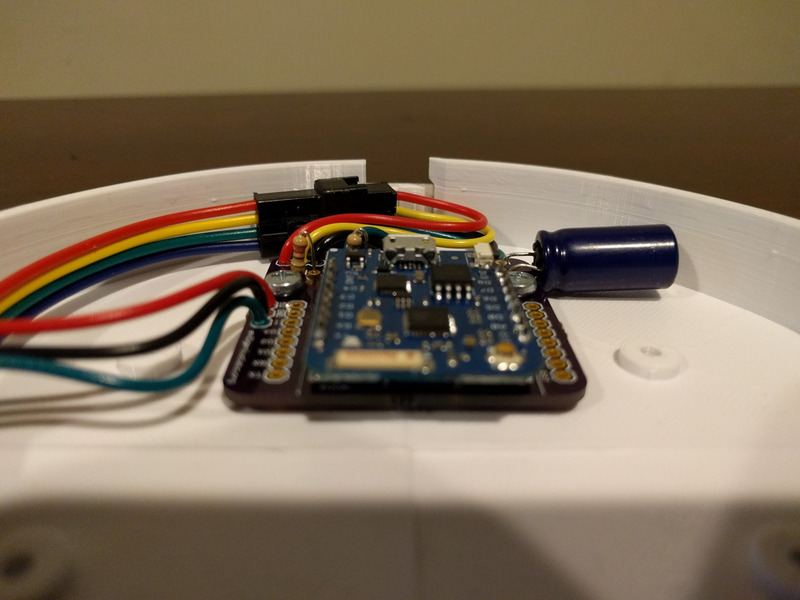
The board can be assembled in a very low profile configuration (about 10mm thick) by soldering the Wemos directly to the PCB with only male headers, and by mounting the large capacitor to the side:
Alternatively, female headers can be used to allow easy removal of the Wemos microcontroller. This results in about 18mm of thickness.
Stacking female headers can be used, which allows plugging other Wemos shields directly on top and/or bottom. This adds another 8mm to 16mm of thickness.

I also designed a 3D printed enclosure for it. It provides access to the wiring for the LEDs, IR receiver, reset button, and Micro USB connector.
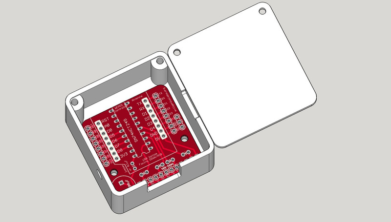
The enclosure STL files are also available for 3D printing on Thingiverse.
Parts that are not included, but are required to assemble:
Wire/Connectors
OR
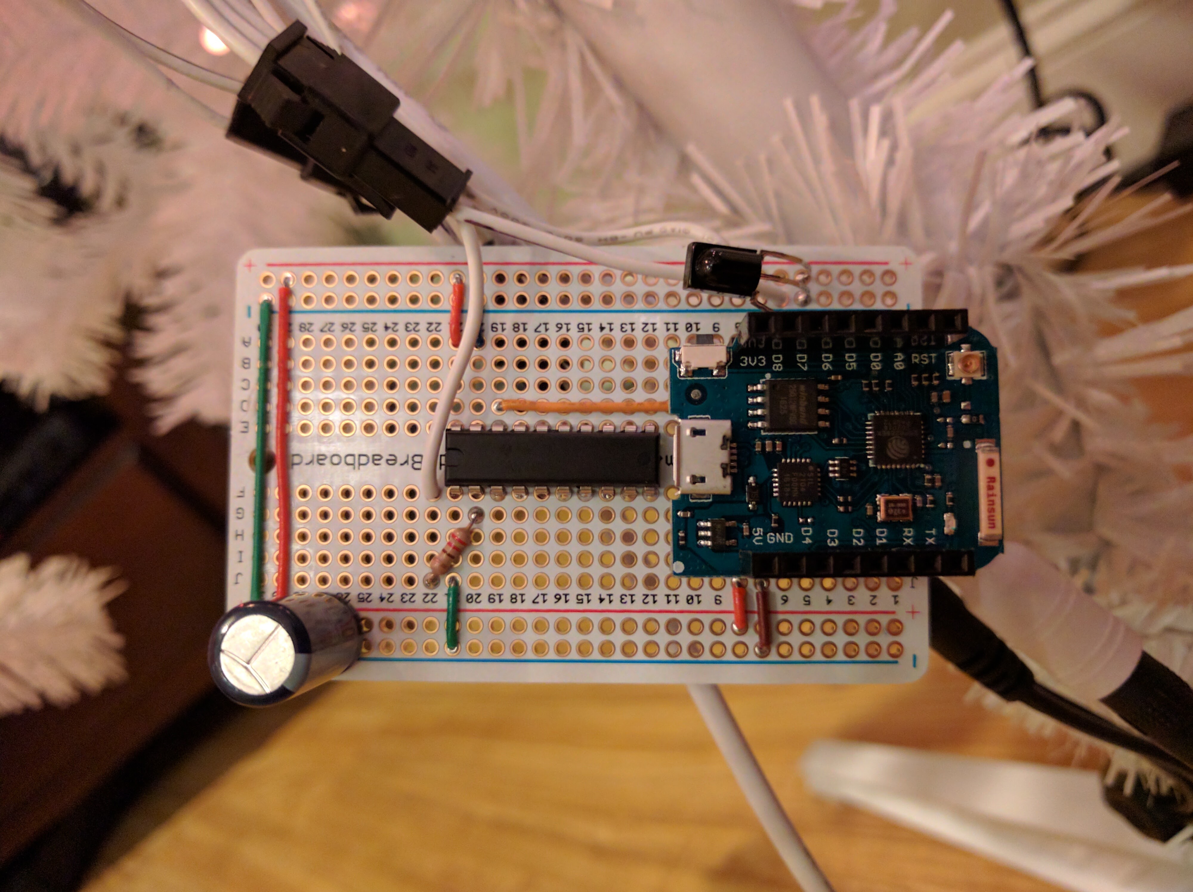
All of my projects lately have been driven by ESP8266 microcontrollers with Wi-Fi support. Following the best practice recommendations of using a fast level shifter, large capacitor, and resistors on the clock and data lines was resulting in a lot of wires on a large perma-proto board. I decided to design a PCB to make it cleaner and more compact.
It’s much smaller and easier to assemble, compared to the perma-proto boards I was building:
After trying a lot of different ESP8266 boards, I’ve found the Wemos D1 Mini to be great for the price. It includes an improved CP2104 USB-TO-UART adapter for more reliable, high-speed firmware and SPIFFs updates, larger (16MB) flash storage, etc.
Open source example firmware and web application: https://github.com/jasoncoon/esp8266-fastled-webserver

Features:
Note: Double-check the position, alignment, and orientation of each component very carefully before soldering!
If you’re new to soldering, I highly recommend reading through a good soldering tutorial, such as the ones by Adafruit and SparkFun.


If you have a v1.0 or older PCB, if your PCB does not have a version number, or if this spot is labeled ‘jumper or 0.1uF’, you must use a jumper wire instead of a capacitor.
If you have a v1.1 or newer PCB, or if this spot is labeled ‘0.1uF’, you can either leave it empty or use a 0.1uF capacitor.


 I left the wires on the spools, which makes it easier to handle. I used a third hand tool to hold the PCB, since this part requires both hands free.


