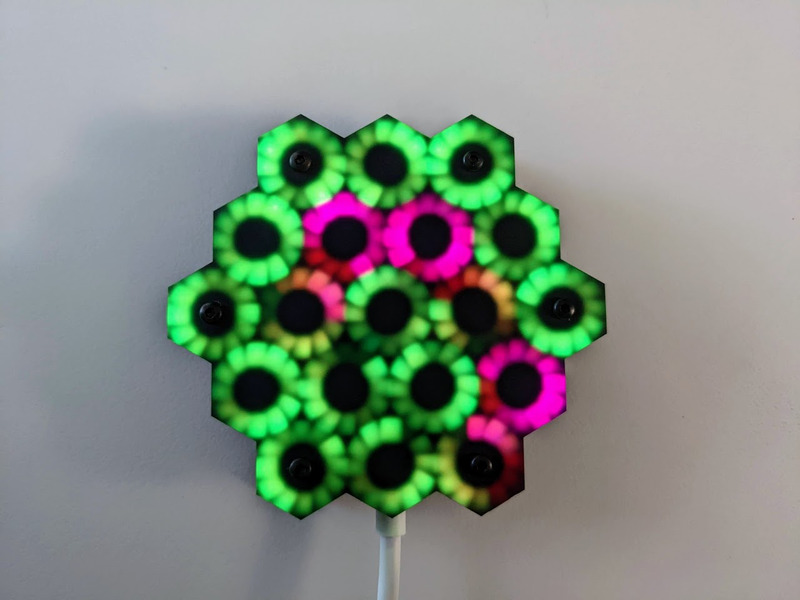
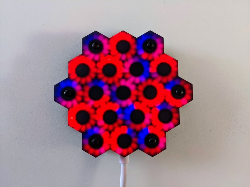
CycloHex is a beautiful set of hexagonally-nested rings with 228 RGB LEDs, six touch pads, and mounting pads for an Adafruit QT Py SAMD21.
I have RGB LEDs in just about every form they come: strips, strings, rings, discs, etc. I constantly seek new and novel forms.
The WS2812C-2020 each only consume a maximum of 15mA, and that’s at 100% brightness, solid white color. That’s 3.42A for all 228 combined. They are incredibly bright, and I usually only run them at about 25% brightness.
It has solder pads on the back that match the pinout of the QT Py by Adafruit, or XIAO by Seeed. It can be used by any microcontroller via the 5V, GND, and Data In pins. It also has a Data Out pad, for connecting more LEDs on the same data pin.
The six mounting holes are surrounded by capacitive touch compatible pads. They’re connected to the A0-A3, A6 & A7 pads/pins on the QT Py footprint. The SAMD21 QT Py supports capacitive touch on these pins. Most other QT Py / XIAO boards, such as the RP2040, do not support capacitive touch.
Specifications
Size: 2.96 x 2.73 x .063 inch (75mm x 70mm x 1.6 mm)
2 layer printed circuit board
FR4 substrate
Black SMOBC (solder mask over bare copper)
HASL (Hot Air Solder Leveling)
Designed and assembled in the US by Evil Genius Labs
Note: Double-check the position, alignment, and orientation of each component very carefully before soldering!
If you’re new to soldering, I highly recommend reading through a good soldering tutorial, such as the ones by Adafruit and SparkFun.
Find a clean spot on your soldering workspace. I used a piece of heavy card stock. Carefully place the board with the LEDs facing down and the bottom of the board facing up.
VERY carefully check polarity before connecting 5V and GND.
Either:
Solder wires to the pads on the back of the Fibonacci PCB and connect them to your microcontroller.
Or:
Carefully align an Adafruit QT Py, Seeeduino XIAO, or another controller with an identical footprint with the pads on the back of the PCB. Solder the pads.
Keep an eye on the temperature of the PCB and especially the connectors. High temperatures can reduce the life of the LEDs. When possible, ensure air can flow, either passively (ventilation) or actively (exhaust fan).
Each WS2812C-2020 can theoretically draw 15mA at full brightness, solid white color. 228 of them can theoretically draw 3,420mA or 3.42A! I suggest using FastLED’s power management to limit the maximum brightness to a reasonable amount, such as 1,200mA, well under the maximum your power supply is rated for. I’ve found that 3,420mA is blindingly bright.
WS
Acrylic Open Case Assembly Instructions
Peel and remove any protective plastic and/or paper film from the acrylic.
Place the acrylic grid onto the LED PCB, aligning the holes with the LEDs and mounting holes.
Keeping the acrylic grid horizontal, place an M2 nut in each of the six hexagonal holes in the grid.
Again, keeping the acrylic grid horizontal so the M2 nuts don’t fall out, place the acrylic front on top of the grid with the matte side facing up.
Carefully insert M2x8mm Button Head Hex Screws into each of the six holes in the matte side of the acrylic face plate.
Loosely hand tighten each of the six screws, making sure they’re each threaded through an M2 nut, through the grid and PCB, and out the back side of the PCB.
Hand-tighten an M2 Nylon Hex Standoff onto each of the screws, on the back side of the PCB.
Center and place the acrylic back plate onto the standoffs.
Insert and hand-tighten an M2x6mm screw through the back plate and in to the standoffs.