Evil Genius Labs
Purveyor of finely hand-crafted pixels. ꩜
Purveyor of finely hand-crafted pixels. ꩜
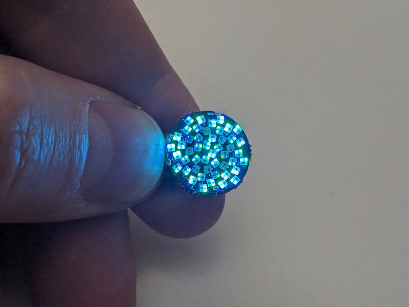
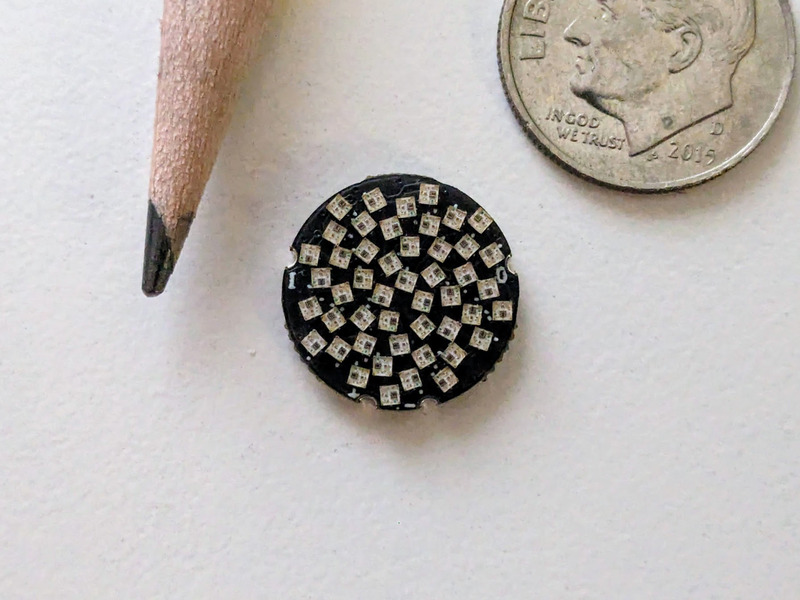
Fibonacci48 x 14mm is a tiny, beautiful circular disc with 48 RGB LEDs surface mounted in a Fibonacci distribution. Swirling and pulsing like a miniature galaxy, it’s mesmerizing to watch.

It consists of 48 XL-1010RGBC-WS2812B 1mm² RGB LEDs, arranged into a circular Fermat’s spiral pattern.
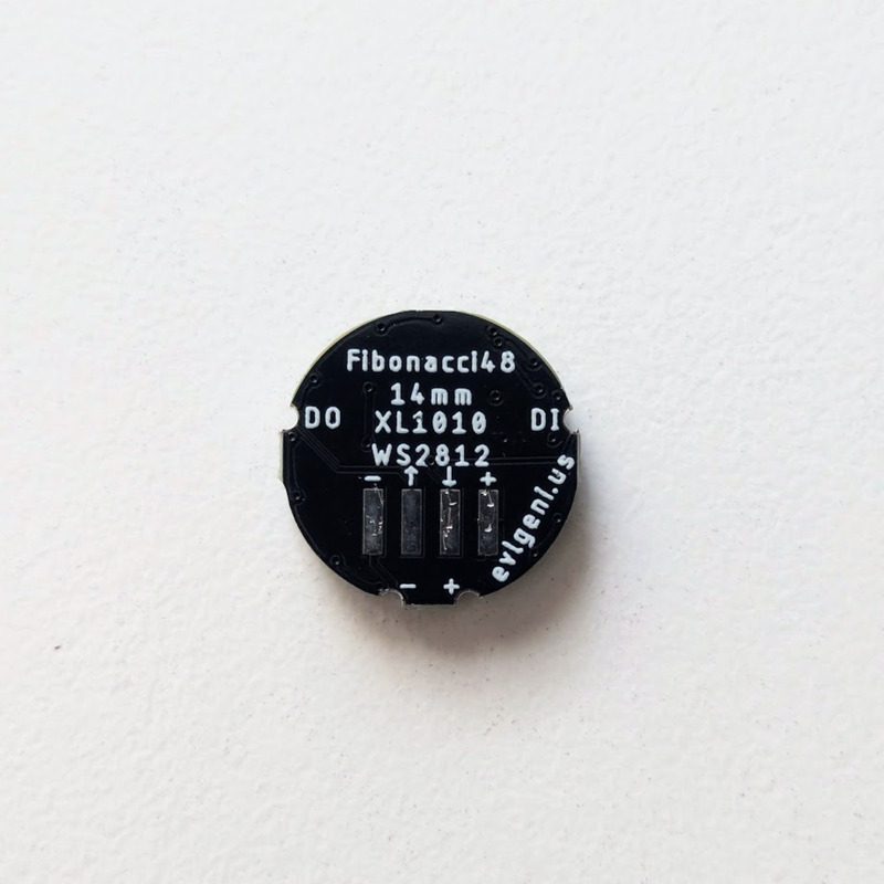
It has solder pads on the back that match the pinout of the TinyLily, although WARNING: I’ve had a hard time driving them with TinyLily when powered via small LIR coin cell batteries. The LEDs glitch at the upper-range of the batteries’ voltage, but work fine at the lower end, or with a resistor inline with the power to drop the voltage.
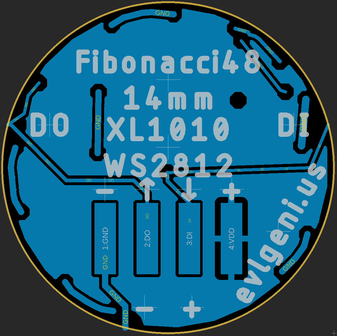
It can be used with any microcontroller via the 5V, GND, and Data In pads. It also has a Data Out pad, for connecting more LEDs on the same data pin.
In disc phyllotaxis, as in the sunflower and daisy, the mesh of spirals occurs in Fibonacci numbers because divergence (angle of succession in a single spiral arrangement) approaches the golden ratio. The shape of the spirals depends on the growth of the elements generated sequentially. In mature-disc phyllotaxis, when all the elements are the same size, the shape of the spirals is that of Fermat spirals—ideally. That is because Fermat's spiral traverses equal annuli in equal turns. The full model proposed by H Vogel in 1979[2] is


where θ is the angle, r is the radius or distance from the center, and n is the index number of the floret and c is a constant scaling factor. The angle 137.508° is the golden angle which is approximated by ratios of Fibonacci numbers.[3]
Fermat's spiral. (2015, October 24). In Wikipedia, The Free Encyclopedia. Retrieved 02:45, February 24, 2016, from https://en.wikipedia.org/w/index.php?title=Fermat%27s_spiral
Open source touch demo: https://github.com/jasoncoon/fibonacci48x14mmDemo
Note: Double-check the position, alignment, and orientation of each component very carefully before soldering!
If you’re new to soldering, I highly recommend reading through a good soldering tutorial, such as the ones by Adafruit and SparkFun.
Note: The order of the pads is: - Ground, ⬆️ Data Out, ⬇️ Data In, + 5V