Evil Genius Labs
Purveyor of finely hand-crafted pixels. ꩜
Purveyor of finely hand-crafted pixels. ꩜


For free shipping worldwide, you can order directly from OSH Park: https://oshpark.com/shared_projects/g39rlmiB
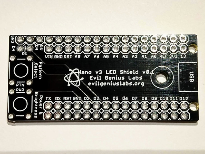
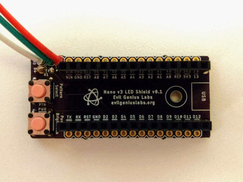
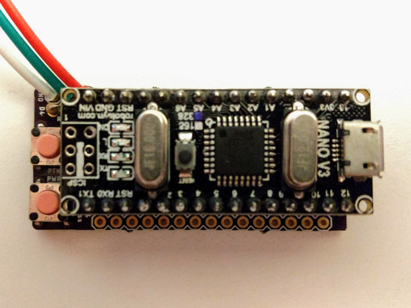
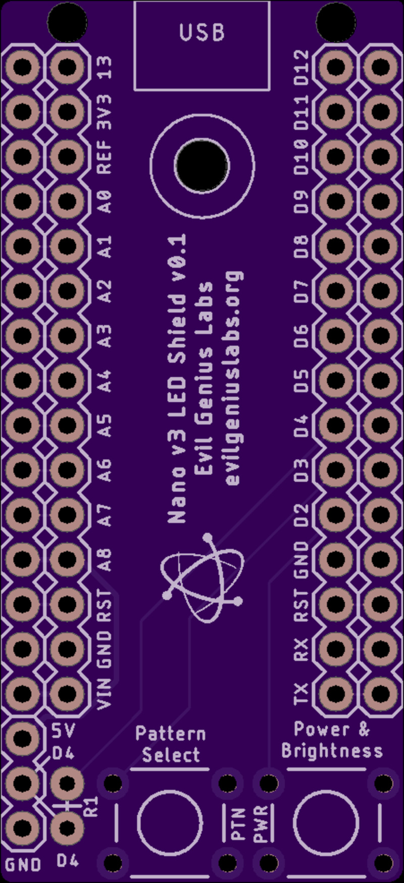
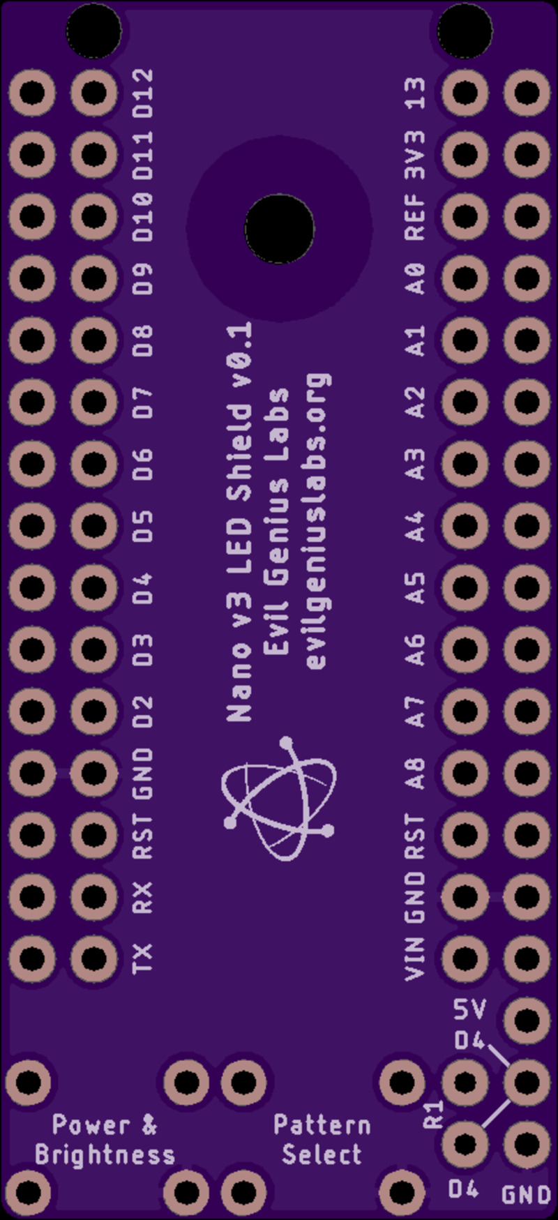
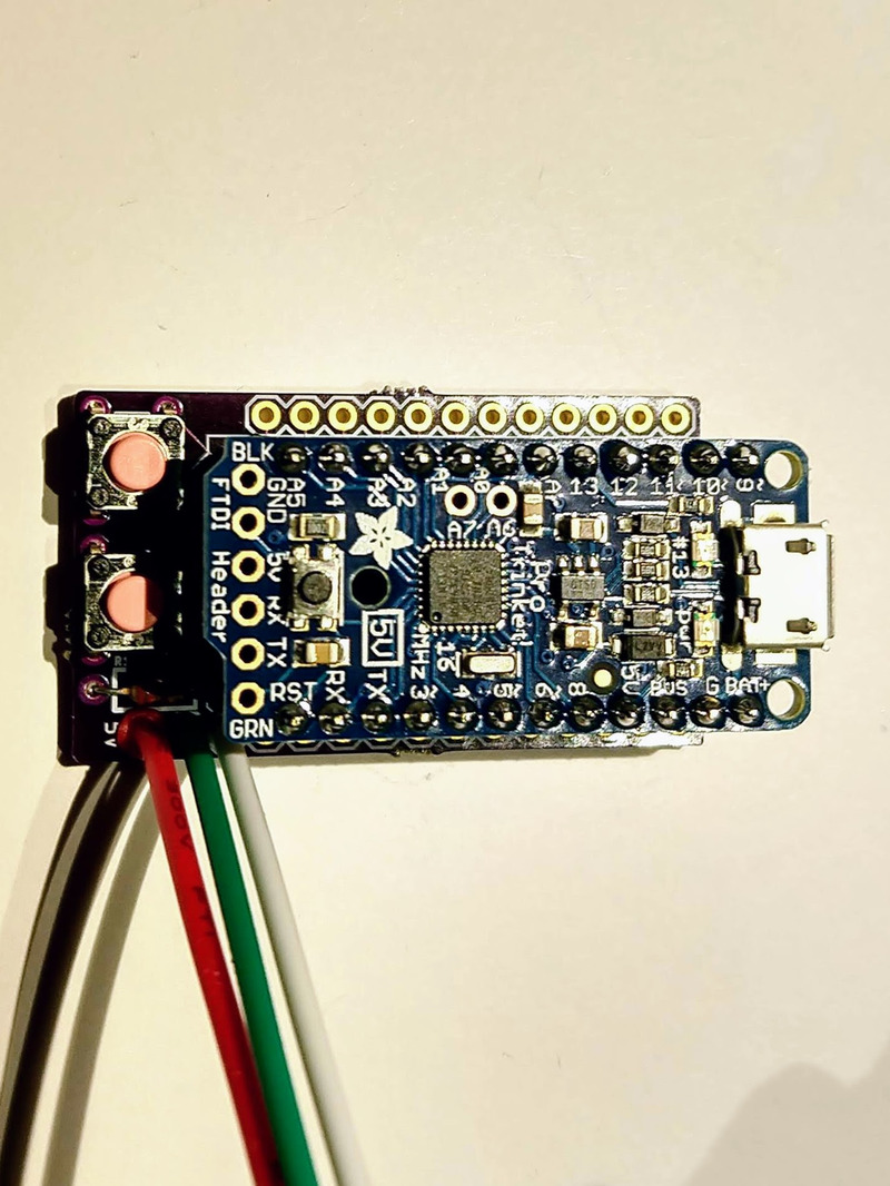
This is a shield/breakout for Arduino Nano v3 that makes it easy to control addressable RGB LEDs, such as WS2811, WS2812 (Adafruit NeoPixels), SK6812, etc. The Arduino Nano v3 is an excellent Arduino compatible development board based on the ATmega328P.
No level shifter is required since the Arduino Nano v3 outputs the same 5 volt logic level that the LEDs require.
I made this shield because I was hand-wiring this same layout on perma-proto boards, which was time-consuming and unprofessional looking.
One digital output pin (D4) is run through a data line resistor, as recommended by Adafruit’s NeoPixel Best Practices.
The large 5V trace and GND pour should be rated for up to 2 amps. That’s enough for about 33 LEDs at max output (solid white, full brightness). For larger quantities, power should be connected directly to the LEDs, and/or brightness should be limited in software.
Parts that are not included, but are required to assemble:
Wire/Connectors
OR
Optional parts:
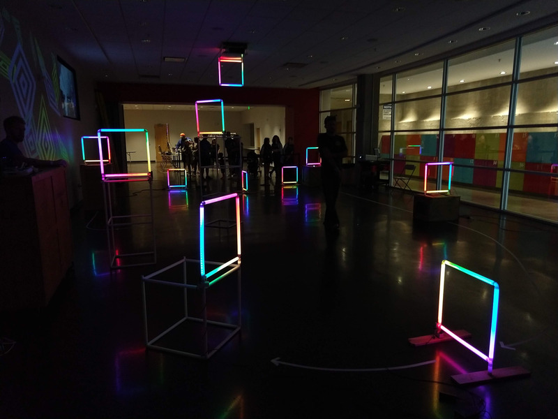
See this post for more details on building the gates: https://www.evilgeniuslabs.org/rgb-led-micro-quadrotor-race-gate
Open source example Arduino sketch: https://github.com/jasoncoon/demoreel100-buttons
Features:
Note: Double-check the position, alignment, and orientation of each component very carefully before soldering!
If you’re new to soldering, I highly recommend reading through a good soldering tutorial, such as the ones by Adafruit and SparkFun.
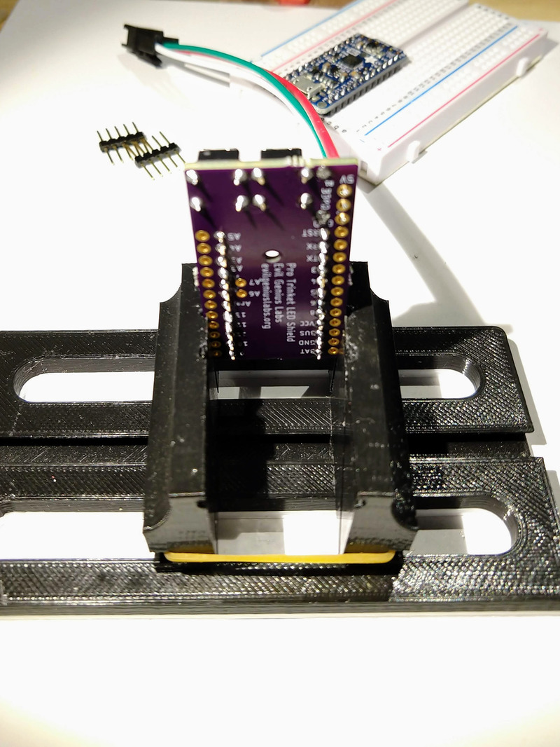
I used this 3D printed vise to hold the PCB while soldering.
I also built one of these DIY flexible soldering helping hands.
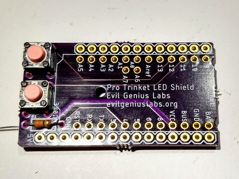
Insert the 300 Ohm to 500 Ohm resistor.
Flip the board over and solder each leg of the resistor.
Insert and solder the button pins.
Trim all the leads with a pair of wire cutters. Flush diagonal cutters work best.
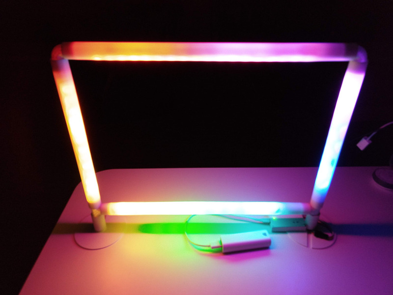
I used a pre-assembled 3 pin JST-SM connector to connect the LEDs.
 Â
ÂWith a small amount of solder on the tip of the iron, heat the wire right on the bottom of the pad.
Melt a fair amount of solder on the wire and pad. The insulation on the wire may start to melt as the wire heats up. If so, push the wire through the hole, from the top towards the bottom, to ensure no wire is left exposed on top.
Repeat this process for the other wires.
See this post for more details on building the gates: https://www.evilgeniuslabs.org/rgb-led-micro-quadrotor-race-gate
I designed and 3D printed a case for the Nano. I assembled the shield with female headers so the Nano could be removed, so the case is a bit bulky. I plan to build more without the female headers, and will make a new lower profile case when I do.
I printed the case, lid, and two button pins. The shield attaches to the case with small M3 screws. The case can be attached to a flange/foot with M3 screws, by marking and drilling a small hole in the flange. I’ll likely end up combining the case and flange into one 3D printed part eventually.
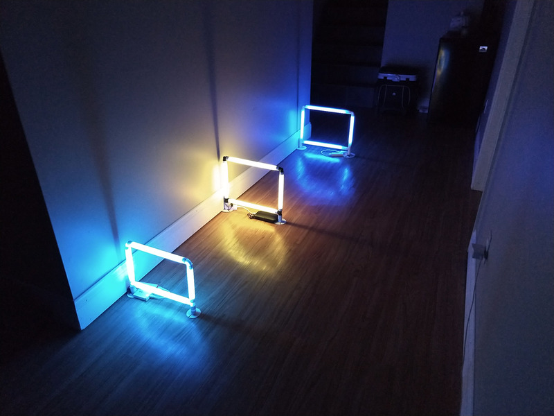
I power each gate with a cheap USB power bank.