
Evil Genius Labs
Purveyor of finely hand-crafted pixels. ꩜
Purveyor of finely hand-crafted pixels. ꩜
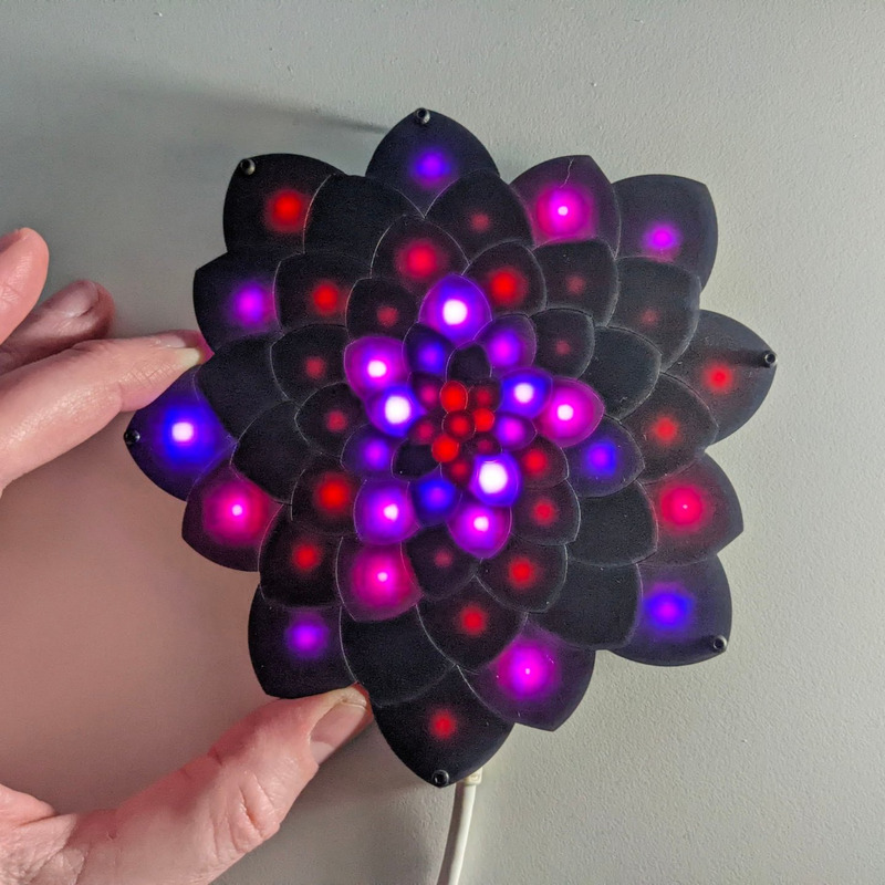
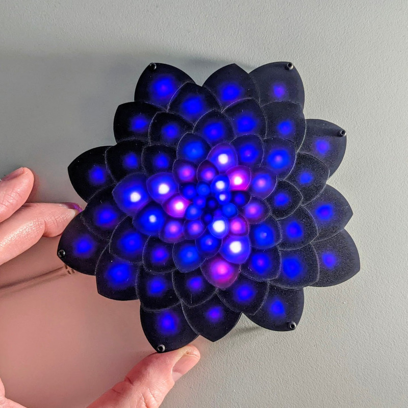

Fibonacci64 Flower is a beautiful 148mm PCB with 64 RGB LEDs surface mounted in a Fibonacci distribution. Swirling and pulsing like a colorful galaxy, it’s mesmerizing to watch.
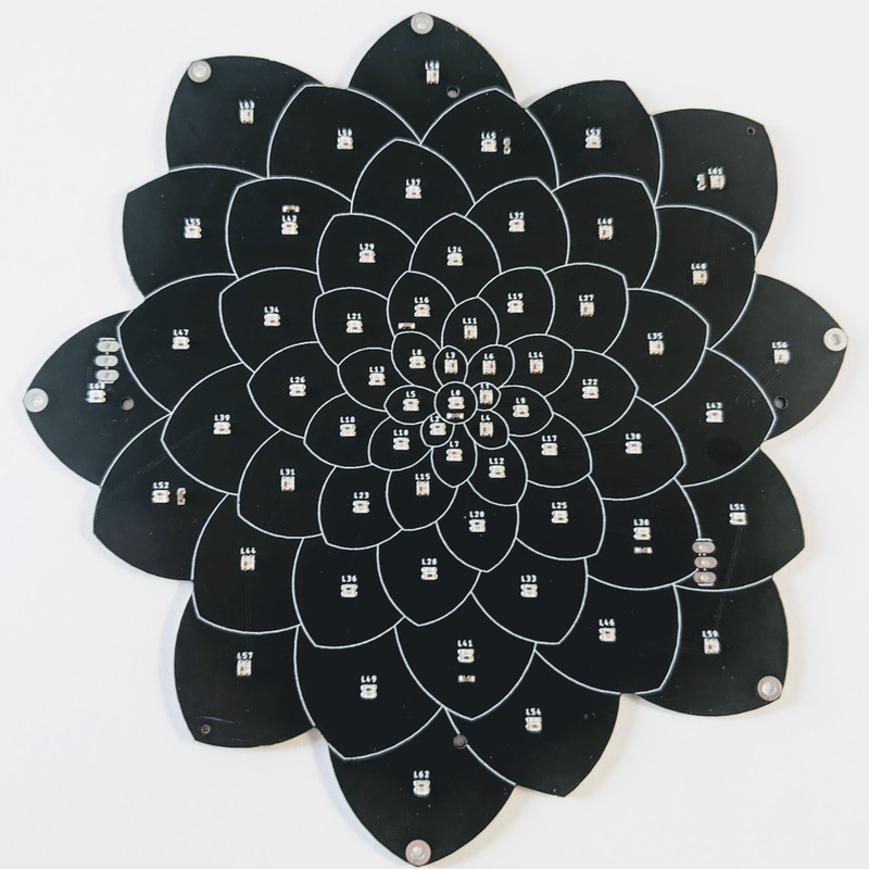
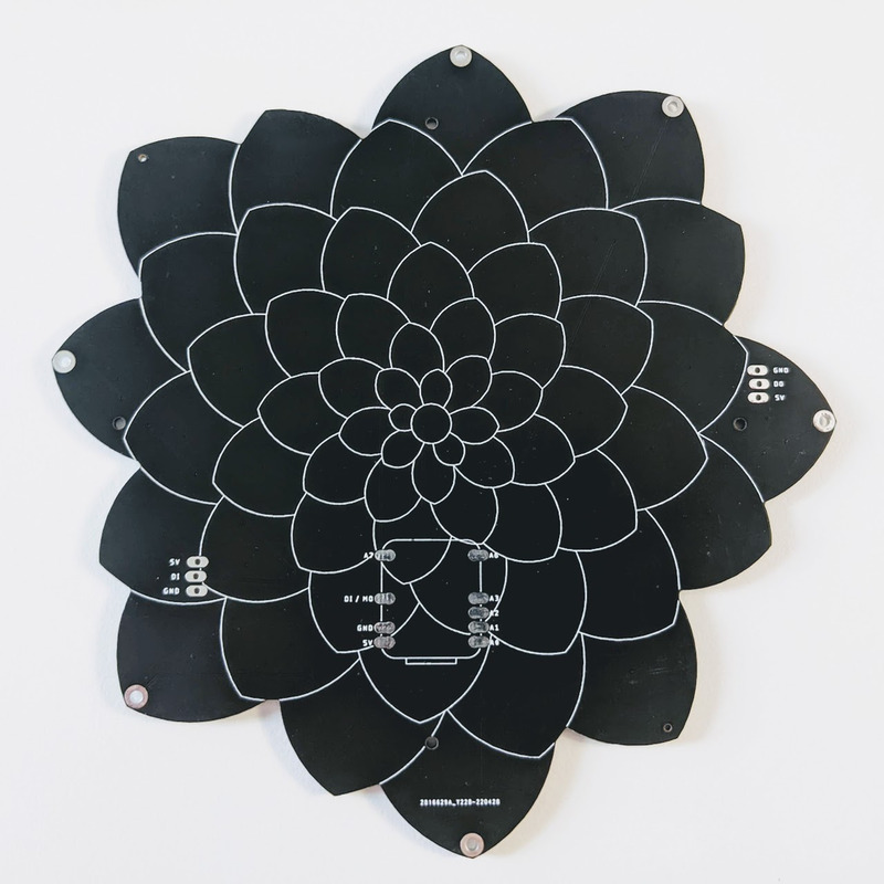
It has solder pads on the back that match the pinout of the QT Py by Adafruit, or XIAO by Seeed. It can be used by any microcontroller via the 5V, GND, and Data In pins. It also has a Data Out pad, for connecting more LEDs on the same data pin.
The six mounting holes are surrounded by capacitive touch compatible pads. They’re connected to the A0-A3, A6 & A7 pads/pins on the QT Py footprint. The SAMD21 QT Py supports capacitive touch on these pins. Most other QT Py / XIAO boards, such as the RP2040, do not support capacitive touch.
It was inspired by and created with a fork of bleeptrack’s overflower project
You can buy stickers of the designs in bleeptrack’s store

It consists of 64 RGB LEDs, arranged into a flower-shaped Fermat’s spiral pattern.
In disc phyllotaxis, as in the sunflower and daisy, the mesh of spirals occurs in Fibonacci numbers because divergence (angle of succession in a single spiral arrangement) approaches the golden ratio. The shape of the spirals depends on the growth of the elements generated sequentially. In mature-disc phyllotaxis, when all the elements are the same size, the shape of the spirals is that of Fermat spirals—ideally. That is because Fermat's spiral traverses equal annuli in equal turns. The full model proposed by H Vogel in 1979[2] is


where θ is the angle, r is the radius or distance from the center, and n is the index number of the floret and c is a constant scaling factor. The angle 137.508° is the golden angle which is approximated by ratios of Fibonacci numbers.[3]
Fermat's spiral. (2015, October 24). In Wikipedia, The Free Encyclopedia. Retrieved 02:45, February 24, 2016, from https://en.wikipedia.org/w/index.php?title=Fermat%27s_spiral
Open source example firmware and web application: https://github.com/jasoncoon/fibonacci64-touch-demo/tree/f64-flower
Note: Double-check the position, alignment, and orientation of each component very carefully before soldering!
If you’re new to soldering, I highly recommend reading through a good soldering tutorial, such as the ones by Adafruit and SparkFun.